Factory Free sample 10.1 Tft Lcd Monitor - T5L UART LCD module – 5.0 Inch – DWIN Detail:
Specification
ASIC Information
| T5L0 ASIC | T5L0 ASIC is a low-power, cost-effective, GUI and application highly integrated single-chip dual-core ASIC designed by DWIN Technology for small-size LCD and mass produced in 2020. | ||
Display
| Color | 262K colors | ||
| LCD Type | IPS-TFT-LCD, | ||
| Viewing Angle | Wide viewing angel, typical value of 85°/85°/85°/85°(L/R/U/D) | ||
| Active Area(A.A) | 61.632mm (W)×109.6536mm (H) | ||
| Resolution | 480×854 | ||
| Backlight | LED | ||
| Brightness | DMG85480F050_01WN:400nit DMG85480F050_01WTC:350nit DMG85480F050_01WTCZ01:350nit DMG85480F050_01WTCZ02:80nit |
||
Touch parameters
| Type | CTP (Capacitive touch panel) | ||
| Structure | G+G structure | ||
| Touch Mode | Support point touch and drag | ||
| Surface Hardness | 6H | ||
| Light Transmittance | Over 90% | ||
| Life | Over 1,000,000 times touch | ||
Voltage & Current
| Power Voltage | 4.5~5.5V, typical value of 5V | ||
| Operation Current | VCC=5V, max backlight, 300mA, | ||
| VCC=5V, backlight off,95mA, | |||
Reliability Test
| Working Temperature | -10℃~60℃ | ||
| Storage Temperature | -20℃~70℃ | ||
| Working Humidity | 10%~90%RH, typical value of 60% RH | ||
Interface
| User interface | 50Pin_0.5mm FPC | ||
| Baudrate | 3150~3225600bps | ||
| Output Voltage | Output 1, Iout = 1mA;3.0~3.3 V | ||
| Output 0, Iout =-1mA;0~0.3 V | |||
| Input Voltage (RXD) |
Input 1, Iin = 1mA;0~3.3V | ||
| Input 0, Iin = -1mA;0~0.5V | |||
| Interface | UART2: TTL; UART4: TTL;( Only available after OS configuration) UART5: TTL;(Only available after OS configuration |
||
| Data Format | UART2: N81; UART4: N81/E81/O81/N82;4 modes (OS configuration) UART5: N81/E81/O81/N82;4 modes (OS configuration) |
||
External Interface
| Pin | Definition | I/O | Functional Description |
| 1 | 5V | I | Power supply, DC3.6-5.5V |
| 2 | 5V | I | |
| 3 | GND | GND | GND |
| 4 | GND | GND | |
| 5 | GND | GND | |
| 6 | AD7 | I | 5 input ADCs. 12-bit resolution in case of 3.3V power supply. 0-3.3V input voltage. Except for AD6, the rest data is sent to OS core via UART3 in real time with 16KHz sampling rate. AD1 and AD5 can be used in parallel, and AD3 and AD7 can be used in parallel, which equals to two 32KHz sampling AD. AD1, AD3, AD5, AD7 can be used in parallel, which equals to a 64KHz sampling AD; the data is summed 1024 times and then divided by 64 to obtain a 64Hz 16bit AD value by oversampling. |
| 7 | AD6 | I | |
| 8 | AD5 | I | |
| 9 | AD3 | I | |
| 10 | AD2 | I | |
| 11 | 3.3 | O | 3.3V output, maximum load of 150mA. |
| 12 | SPK | O | External MOSFET to drive buzzer or speaker. The external 10K resistor should be pulled down to the ground to ensure that power-on is low level. |
| 13 | SD_CD | I/O | SD/SDHC interface,The SD_CK connects a 22pF capacitor to GND near the SD card interface. |
| 14 | SD_CK | O | |
| 15 | SD_D3 | I/O | |
| 16 | SD_D2 | I/O | |
| 17 | SD_D1 | I/O | |
| 18 | SD_D0 | I/O | |
| 19 | PWM0 | O | 2 16-bit PWM output. The external 10K resistor should be pulled down to the ground to ensure that power-on is low level. The OS core can be controlled in real time via UART3 |
| 20 | PWM1 | O | |
| 21 | P3.3 | I/O | If using RX8130 or SD2058 I2C RTC to connect to both IOs, SCL should be connected to P3.2,and SDA connected to P3.3 in parallel with 10K resistor pull-up to 3.3V. |
| 22 | P3.2 | I/O | |
| 23 | P3.1/EX1 | I/O | It can be used as an external interrupt 1 input at the same time, and supports both low voltage level or trailing edge interrupt modes. |
| 24 | P3.0/EX0 | I/O | It can be used as an external interrupt 0 input at the same time, and supports both low voltage level or trailing edge interrupt modes. |
| 25 | P2.7 | I/O | IO interface |
| 26 | P2.6 | I/O | IO interface |
| 27 | P2.5 | I/O | IO interface |
| 28 | P2.4 | I/O | IO interface |
| 29 | P2.3 | I/O | IO interface |
| 30 | P2.2 | I/O | IO interface |
| 31 | P2.1 | I/O | IO interface |
| 32 | P2.0 | I/O | IO interface |
| 33 | P1.7 | I/O | IO interface |
| 34 | P1.6 | I/O | IO interface |
| 35 | P1.5 | I/O | IO interface |
| 36 | P1.4 | I/O | IO interface |
| 37 | P1.3 | I/O | IO interface |
| 38 | P1.2 | I/O | IO interface |
| 39 | P1.1 | I/O | IO interface |
| 40 | P1.0 | I/O | IO interface |
| 41 | UART4_TXD | O | UART4 |
| 42 | UART4_RXD | I | |
| 43 | UART5_TXD | O | UART5 |
| 44 | UART5_RXD | I | |
| 45 | P0.0 | I/O | IO interface |
| 46 | P0.1 | I/O | IO interface |
| 47 | CAN_TX | O | CAN interface |
| 48 | CAN_RX | I | |
| 49 | UART2_TXD | O | UART2(UART0 serial port of OS core) |
| 50 | UART2_RXD | I |
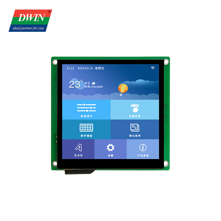
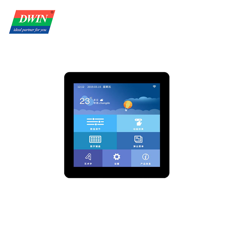
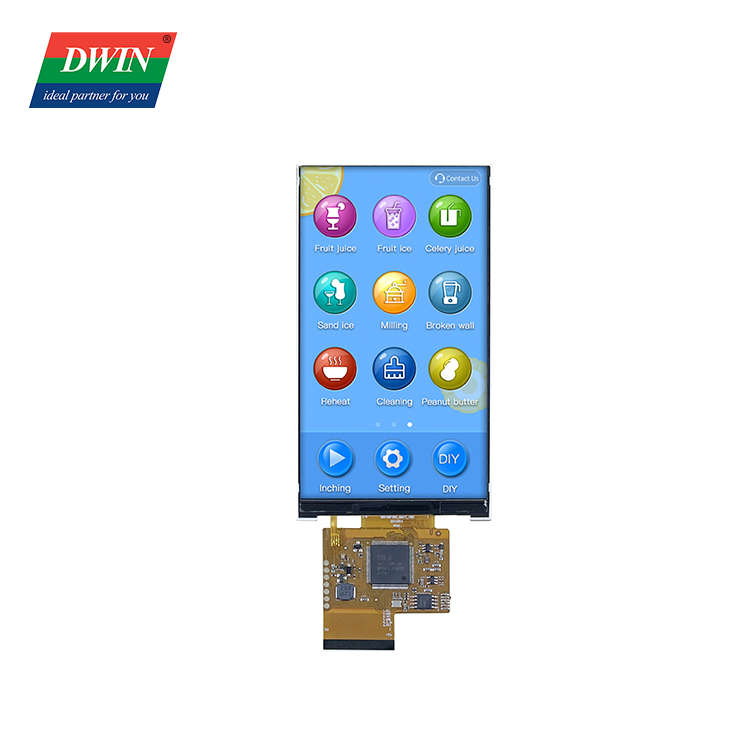
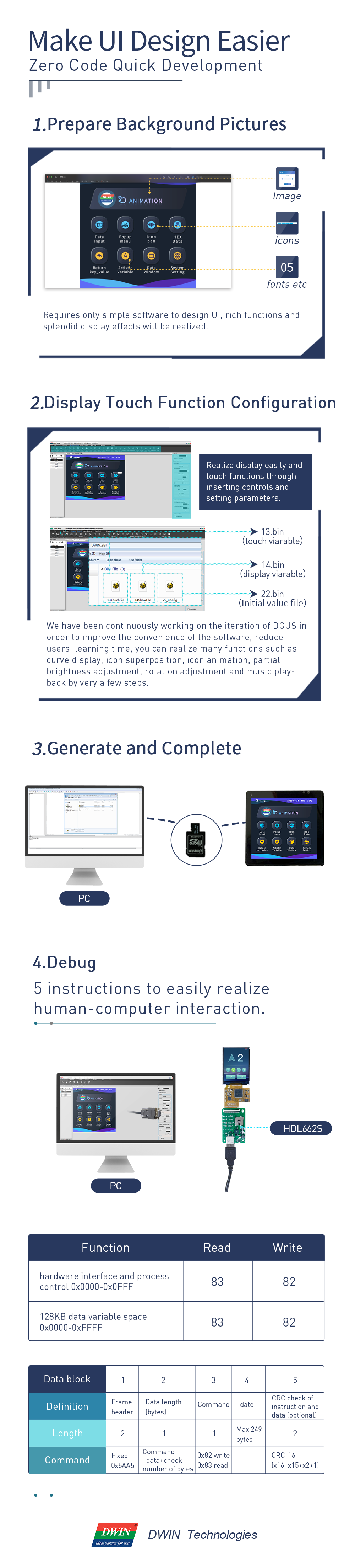
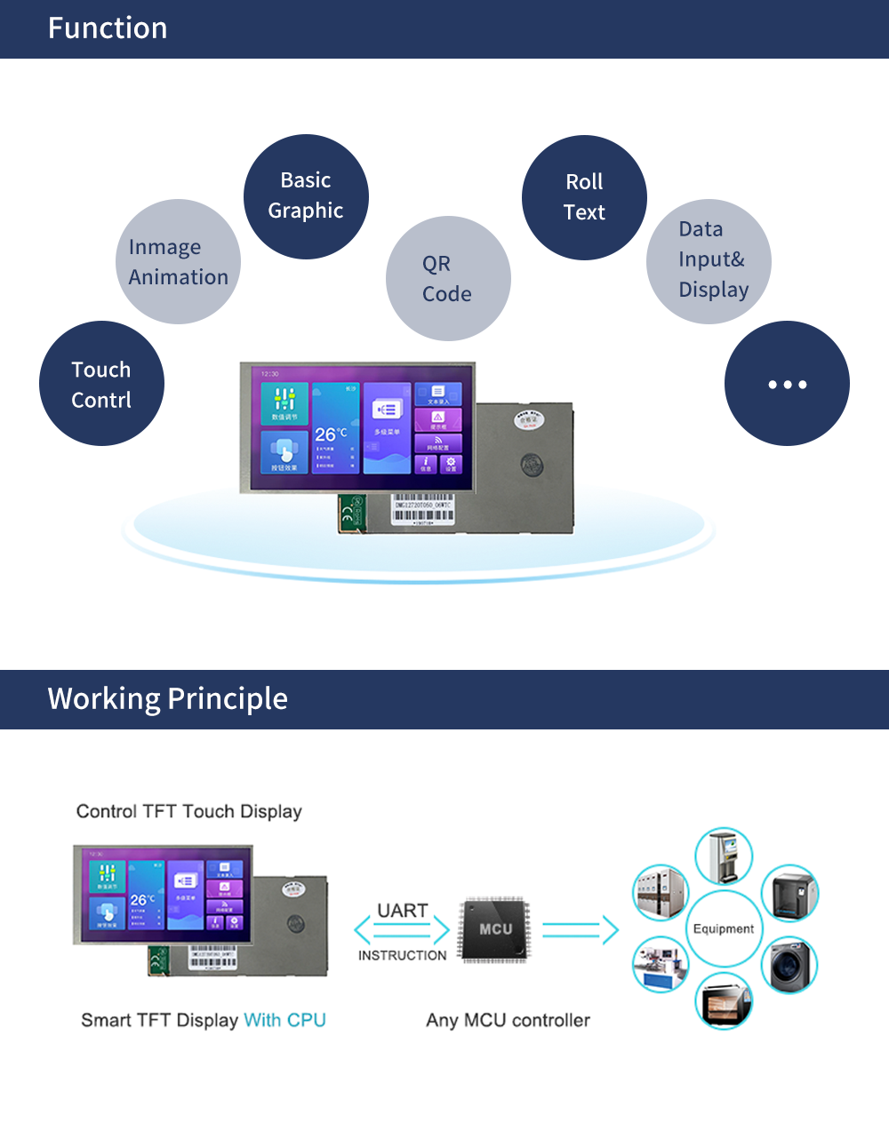
Application

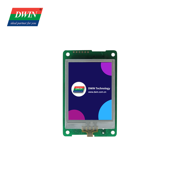
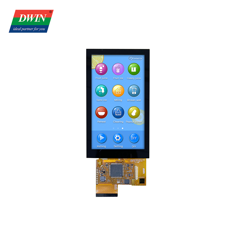
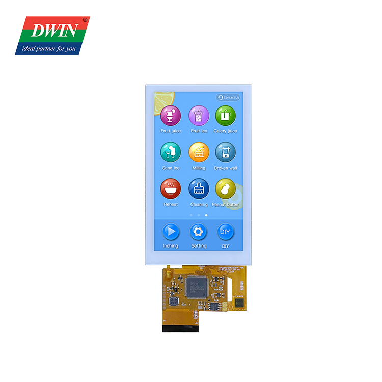
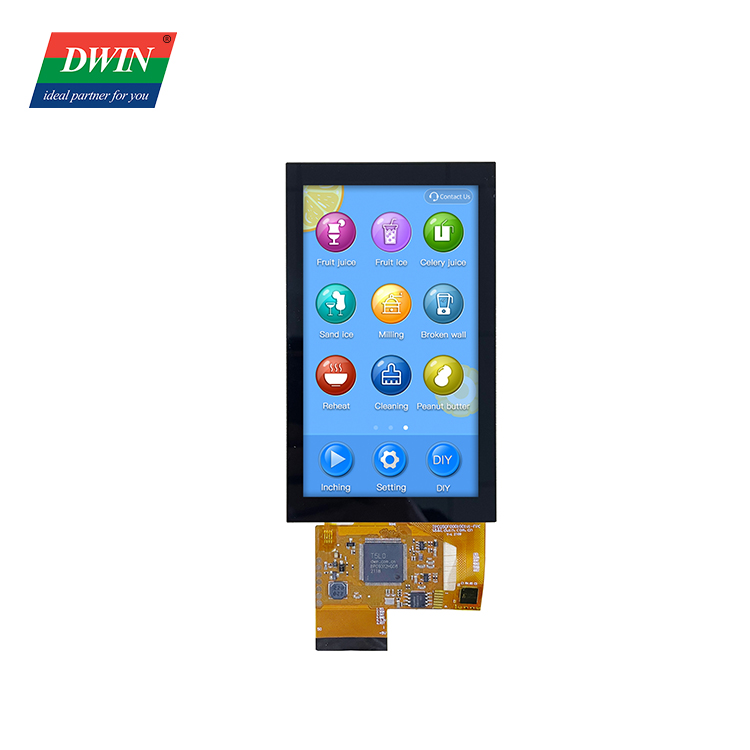
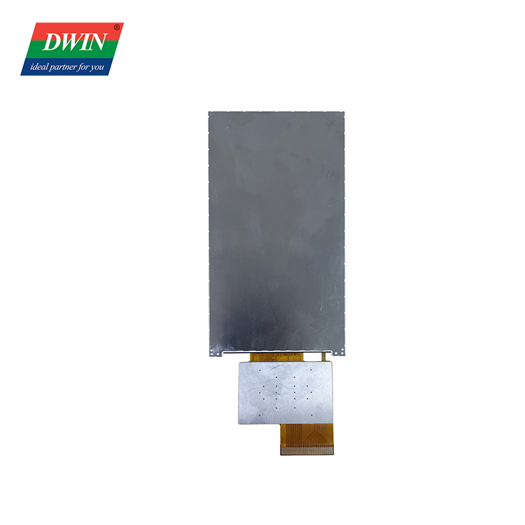
Product detail pictures:
Related Product Guide:
With our leading technology at the same time as our spirit of innovation,mutual cooperation, benefits and development, we are going to build a prosperous future alongside one another with your esteemed enterprise for Factory Free sample 10.1 Tft Lcd Monitor - T5L UART LCD module – 5.0 Inch – DWIN, The product will supply to all over the world, such as: Zambia , Stuttgart , Suriname , Excellent quality comes from our adherence to every detail, and customer satisfaction comes from our sincere dedication. Relying on advanced technology and industry reputation of good cooperation, we try our best to provide more quality products and services to our customers, and all of us are willing to strengthen exchanges with domestic and foreign customers and sincere cooperation, to build a better future.
As a tech enthusiast, I've tried various displays, but DWIN's quality stands out. Worth every penny!